Week 8: Embedded Programming
Assignment:
- Read a microcontroller data sheet.
- Program your board to do something, with as many different programming languages and programming environments as possible.
- Optionally, experiment with other architectures
For this week I have to program the Hello-World board I have already designed on Week 6 and make it work. My board has a red LED and a button. I should learn how to program it in both Arduino IDE and C or C++.
Software:
- Arduino IDE for Mac
- Xcode
Materials:
- Hello-World board button + LED
- FabISB board
- Mini USB cable
- FTDI cable
- Female to female jumper cable
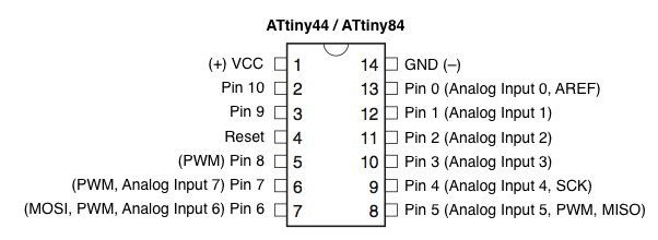
First of all I reviewed the ATtiny44 microcontroller data sheet in order to learn its features and the pins distribution to be able to connect and program the Hello-World board and do something with the button and LED.
The ATtiny44 has the following features:
- 4K of in-system, self-programmable flash program memory
- 256 Bytes of in-system programmable EEPROM
- 256 Bytes of internal SRAM
- Operating voltage 1.8 - 5.5V
- 12 programable pins
Pin Configuration:
To program the Hello-World board with Arduino IDE for Mac, follow this steps:
If you don’t have already installed Arduino IDE, you can download the software here.
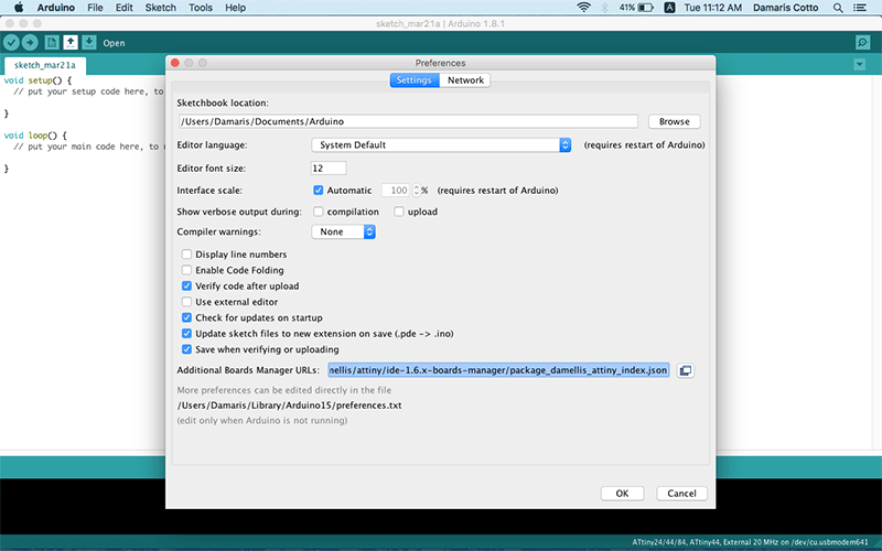
1. Once installed the software, in menu Arduino-Preferences copy and paste the link https://raw.githubusercontent.com/damellis/attiny/ide-1.6.x-boards-manager/package_damellis_attiny_index.json
in Additional Boards Manager URLs blank space to be abele to download al the ATTiny configuration.
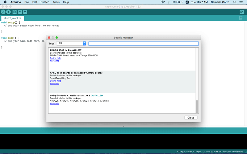
2. In menu Tools - Boards Manager scroll down until find attiny and choosing it, will appear an install button.
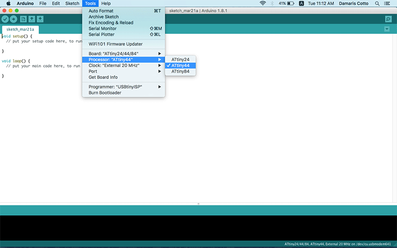
3. Once the installation finishes, go to Menu - Tools - Board select ATTiny24/44/84.
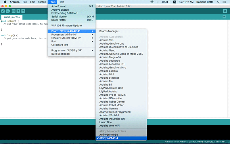
4. Then in Menu - Tools - Processor select ATtiny44.
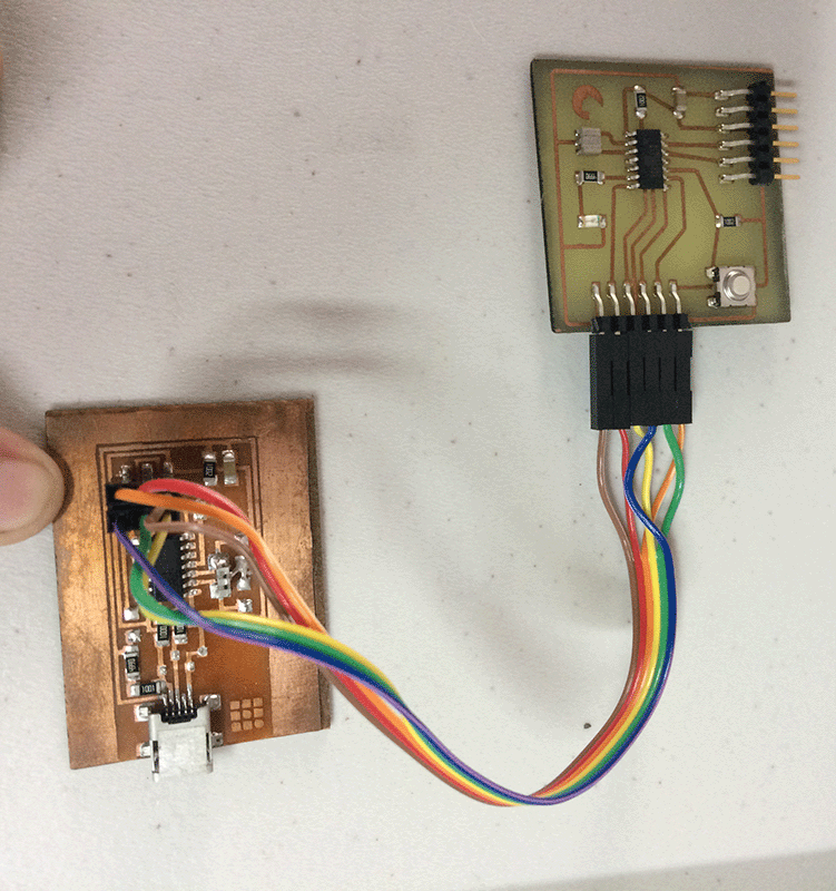
5. Now it’s time to provide power to both FabISP and Hello-World boards connecting them to a USB ports in your computer using a mini USB cable for FabISP and the FTDI cable for the Hello-World board. Both have to be connected each other connecting MISO, MOSI, SCK, RST, VCC and GND to the corresponding pins.
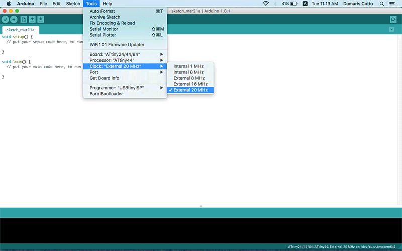
6. In Menu - Tools - Clock select External 20 MHz because the Hello-World board has a 20 MHz crystal resonator component.
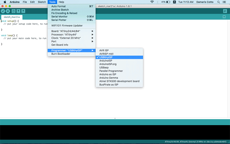
7. In Menu - Tools - Programmer select USBtinyISP because the board which we well program with is an in-system programmer (ISP) and we’ll use the FabISP we made in class.
8. Now you should be able to burn the bootloader to configure the fuse bits of the microcontroller so it runs at 8 MHz. To do that go to Menu - Tools - Burn Bootloader and a message “Done burning bootloader.” should appear in the bottom.
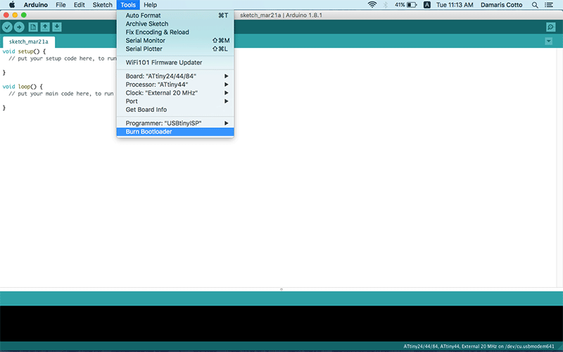
Now the ATtiny44 is ready to be programmed!
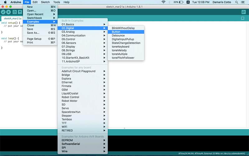
As I have no experience with programming languages, first I open one of the samples that Arduino IDE already have, I used a digital button sample (Menu File - Examples - 02.Digital - Button) and I started to change its code to make my Hello-World board do something.
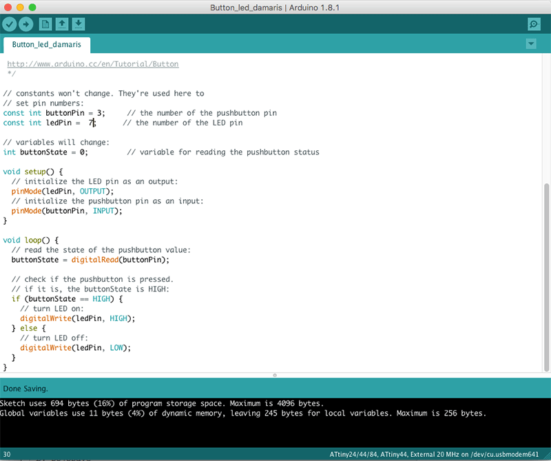
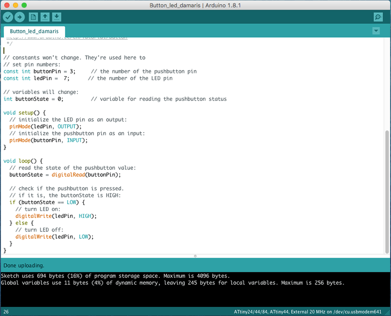
First of all the I changed the pins number for both button and led because the example has by default pin 2 for the button and pin 13 for the LED and the ones we have to use with the ATtiny44 is pin 3 for the button and pin 7 for the led. Once changed I compiled and upload to the board with the arrow in the very top of the Arduino IDE window.
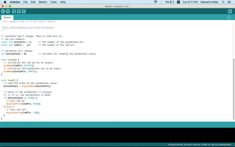
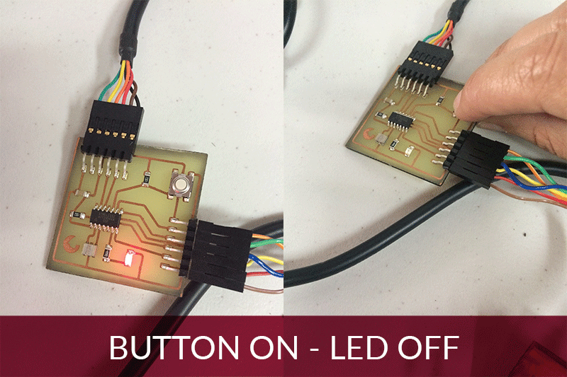
This example has by default to have the LED always ON and pushing the button it turns OF:
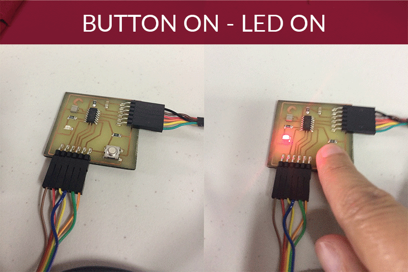
But I rather to be the opposite, the LED should be ON until the button is ON too, so I changed the code to buttonState == LOW:
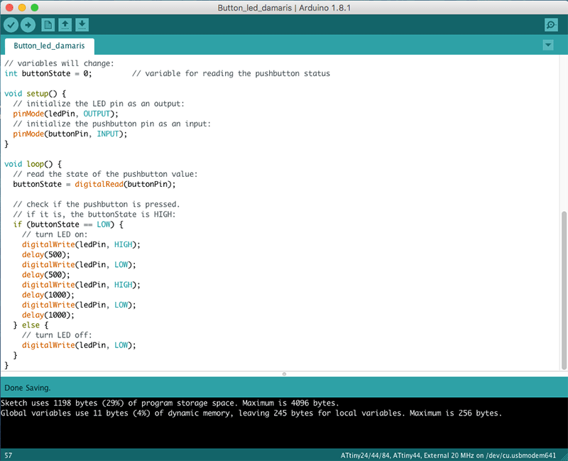
Now I think to make the LED blink twice with a delay between blinks, the time of blink and delay is measured by milliseconds, so 1 second is 1000 milliseconds:
Finally I think I should program the board in a more interesting way, my idea was pushing the button the first time, the led blinks 1 time, pushing a second time, the led blinks 2 times and increasing blinks until reach 5 times, then next time I push the button, it starts again.
In this code I define first the variables “n” and declared n=1 because I wanted to start with 1 time pushing the button, and the variable “i” declared as i=0 which is the internal counter to increase the blink times.
Blinking progressive LED from Damaris Cotto on Vimeo.
This assigment was sponsored by: